Planetary rovers are crucial to humankind’s exploration of the solar system. A novel rover mechanism used to traverse the surface of a planet is one of many research interests of the Engineering Mechanics and Space Systems Laboratory (EMSSL) at N.C. State. A key project currently being developed is the Tumbleweed Rover. With a spherical design, the Martian winds, for example, will be able to push the Tumbleweed Rover over further distances and uneven terrains more so than a traditional rover with the current rocker-bogie mechanism. To steer the Tumbleweed Rover, systems have been developed so that moving weights within the outer shell can slightly change the center of gravity and affect the direction for which the Rover moves. The systems within the Tumbleweed Rover will also benefit the exploration of planets with little to no wind.
A testing platform in the lab simulates the inner workings of the Tumbleweed Rover mass system but on a larger, more usable scale. My project is to design an angular attachment, seen below, that will incline the testing platform from 0 to 90 degrees at 10 degree increments. The goal is to test and observe the effects of gravity on the moving mass. The current mass system on the platform has a tendency to shake back and forth as a sensor tries to read its location. An angular attachment must hold the platform steady to get accurate readings and avoid destabilization.
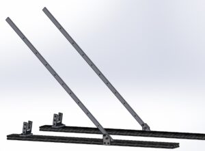
Below is a SolidWorks rendering of the how the testing platform and angular attachment fit together.
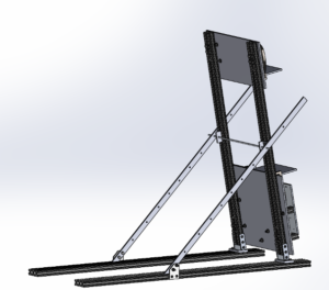
The following design requirements were identified to best incline the testing platform:
- Must be sturdy and hold the heavy platform in place at larger angles
- Must allow for 10 degree increments from 0 to 90 degrees
- Must be modular and detachable so it can be put into storage if necessary
In the concept generation phase, I brainstormed 10 different ideas that fit the above criteria. Ideas included gear trains, pulley systems, and plated aluminum support bars. At the end of the first week, three ideas were chosen by my mentor and I. Next, I elaborated three of these designs in greater detail to determine attachment mechanisms, a rough estimate of costs, and the supporting parts. After presentation of the elaborated designs, my mentor and I chose the best option: a stationary support bar at 45 degrees that would intersect with the sides of the platform.
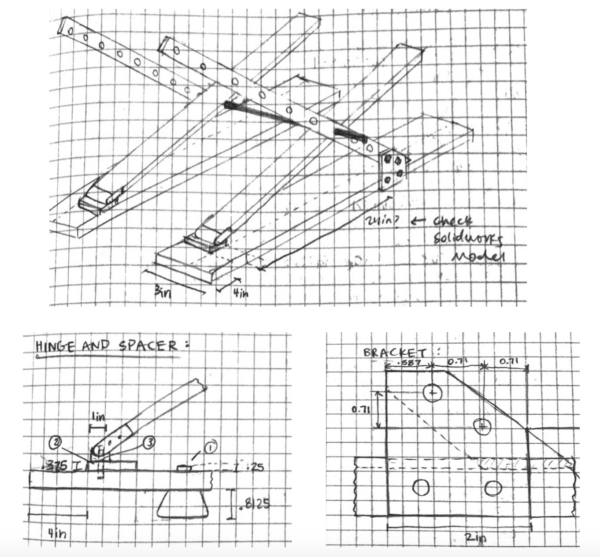
The project completed the ideation phase and was ready to begin detailed design. With the current configuration, we had to be watchful of possible points of stress, especially at the rod and hinge bolt locations. In SolidWorks Simulation, I tested the part models under the maximum force applied by the platform. The bolt simulation is seen below.
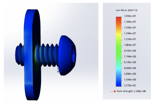
After the force analysis and simulation, I finalized the materials list to get final approval to buy parts. When they arrived, four parts needed to be sent for fabrication to drill holes for assembly. This was done by a waterjet cutting machine and milling machine.
Building the prototype, I first made the base of extruded aluminum with each spacer, hinge, and support bar bracket. It’s important for these pieces to be placed correctly because this is the “triangular base” of the attachment which will allow the platform to reach from 0 to 90 degrees. Next, I attached the steel support bar to the support bracket. The bar will have 9 holes for each 10 degree increment.
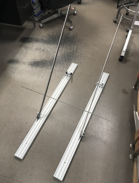
Now that the angular attachment was done, the process of lining up the platform base with the hinge spacers was next. I measured the correct distance for the rod hinge at desired degree angles which attaches to the bottom of the platform. The rod hinge is how the platform rests on the support of the angular attachment. It is crucial that the holes of the rod hinge and support bar line up.
As the final assembly came together, I was able to successfully position the platform at various angles. All parts that were ordered and those that were later machined came together as I had modeled.
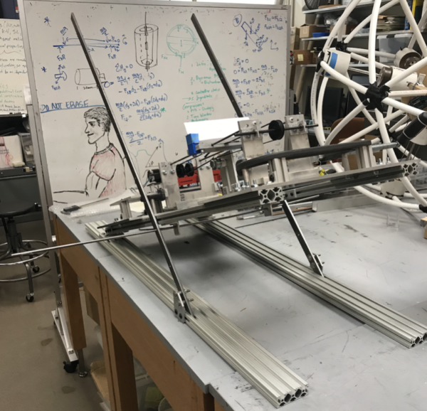
I made one modification during the assembly process by moving the rod hinge from the outer slot to the inner slot on the platform to avoid interference at zero degrees. The calculations and careful planning in the background phase helped streamline the assembly phase.
Over the past two semesters, I was able to truly implement the engineering design process and I look forward to making modifications for a version 2 of the angular attachment. This has been an invaluable experience and I’m grateful for the guidance of my supervisor, Daria Talaski, and faculty advisor, Dr. Andre Mazzoleni.
Comments by cemoore9